+86-0574-63316601


 中文简体
Content
Few things stop a repair in its tracks like an unlabeled set of alternator wires. You have a heavy battery cable, a small molded connector, and maybe a wire that bolts directly to the case. Connect one in the wrong place and you can damage the regulator, drain the battery, or leave the vehicle without a charge. The good news is that identifying alternator wires is a straightforward process: the functions follow predictable rules, the colors follow familiar conventions, and a simple multimeter confirms everything before you make a connection. Here is how to do it step by step.
Know the Role of Each Alternator Wire First
Before you touch anything, it helps to picture how an alternator is wired into a vehicle. Most alternators use the same set of basic functions, even when the connector shapes look different.
- B+ output: the thick wire that carries charging current from the alternator to the battery positive terminal.
- Ignition feed: a switched 12 V feed that wakes up the voltage regulator when the key is turned on.
- Charge lamp wire: the circuit that drives the dashboard warning lamp.
- Voltage sense wire: a sensing lead that tells the regulator the battery voltage so it can adjust output.
- Ground: often achieved through the case, but many alternators also have a dedicated ground terminal.
| Function | Common Labels | What It Does | Visual Clue |
|---|---|---|---|
| B+ output | BAT, B+ | Charging current to battery | Thickest wire, often red |
| Ignition feed | IG, IGN | Turns regulator on with key | Medium gauge, key-on power |
| Charge lamp | L, IND | Drives dash warning lamp | Thin white or brown wire |
| Voltage sense | S, SEN | Regulator reads battery voltage | Thin wire, fused or direct |
| Ground | GND, E | Completes the circuit | Black or bolted to case |
Use Visual Inspection as Your First Clue
Check the Connector and Terminal Labels
Look closely at the alternator case. Many regulators have the terminal letters molded into the plastic or printed on a small sticker next to the connector. You may also find pin numbers on the connector itself, which can be matched against the vehicle's service manual.
Read the Wire Colors
Automotive wire colors are not a universal law, but the conventions are consistent enough to give you a strong starting point. The B+ wire is almost always the thickest wire because it carries the highest current. Ground wires are typically black. The ignition wire commonly appears in yellow, pink, or red with a light tracer, and the lamp wire is often white or brown. When a harness has been replaced before, colors can differ from the factory specification, so treat color as a clue rather than proof.
Compare Connector Positions
The plastic connector is keyed, so it fits only one way, but the same alternator can use different pins depending on the vehicle. Combine the pin numbers with a wiring diagram before assuming which pins are used. If the connector has four pins but only two wires, confirm that the remaining pins are truly unused instead of puzzling over them.
Confirm Each Wire with a Multimeter
Visual identification gets you close; a multimeter makes it certain. Set the meter to DC volts and use the alternator case or the battery negative terminal as your ground reference.
- Connect the black lead to the battery negative terminal and the red lead to each wire you need to identify.
- A wire that reads battery voltage with the key off is the B+ output. This is the only wire that should be hot at all times.
- Turn the key to the ON position without starting the engine. Any wire that now shows battery voltage is the ignition feed (IG).
- The lamp wire behaves differently: it usually has voltage on one side with the key on and the lamp illuminated, and the alternator pulls it low once charging starts. If you cannot get a steady reading, use the resistance mode to check continuity between that pin and the lamp circuit.
- Finally, set the meter to continuity and touch the leads to each remaining wire and the case. A beep confirms a ground wire.
Take notes as you go, and label each wire with masking tape before you disconnect anything. This is exactly the discipline wire harness manufacturers apply when assembling a new harness, because a single misidentified lead can create a short circuit.
Common Alternator Wiring Configurations
Depending on the vehicle and alternator family, you will usually encounter one of three connector layouts.
| Configuration | Typical Wires | Notes |
|---|---|---|
| 2-wire | IG + L | Common on older, smaller alternators |
| 3-wire | B+, IG, L | The classic setup; B+ often exits separately |
| 4-wire | B+, IG, L, S | Adds voltage sense for better regulation |
Remember that the wire count refers to the regulated connector circuits, not the thick B+ output, which may bolt directly to the alternator. On many alternators, B+ is a stud rather than a pin in the plastic connector.
Stay Safe While Inspecting Alternator Wires
- Disconnect the battery negative terminal before removing or installing any wire.
- Never short the B+ terminal to the case; the alternator case is the ground return and can weld tools instantly.
- Use insulated tools and remove a ring terminal by loosening the nut, not by prying.
- Consult the service manual for the exact pinout of your vehicle, because connector layouts vary between manufacturers.
Why Clear Wire Identification Matters in a Well-Built Harness
Alternator wiring is not the only place where identifying wires correctly matters. Inside a washing machine, a heater, or a coffee machine, the same logic applies: every wire has one function, and the harness must make that function obvious. At our wire harness factory, every production harness is built with color-coded leads, numbered terminals, and consistent polarity markers so that technicians can trace circuits quickly and manufacturers can install them without confusion. For a closer look at how the same wiring principles apply beyond the vehicle, read our discussion on the connection between auto parts wiring harnesses and vehicle systems.
Take a washing machine harness as an example. It carries power to the motor, the pump, the heating element, and the sensors. If a repairer cannot tell which wire feeds the heater, they risk energizing the wrong circuit mid-cycle.
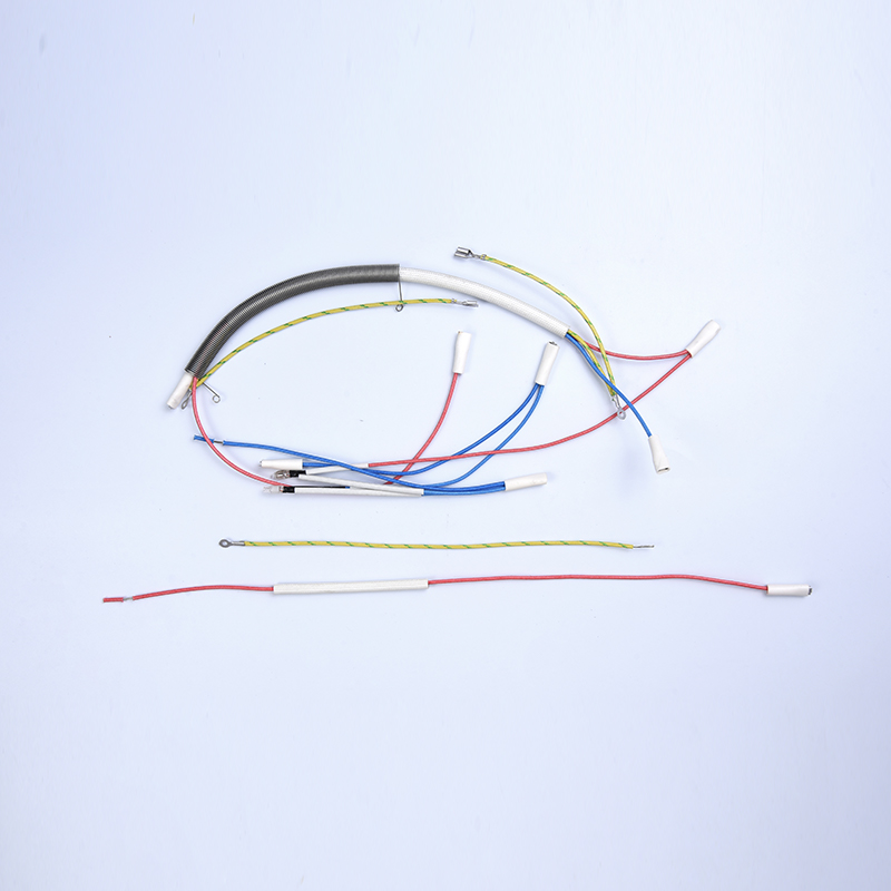
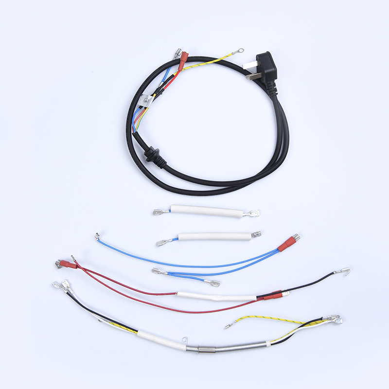
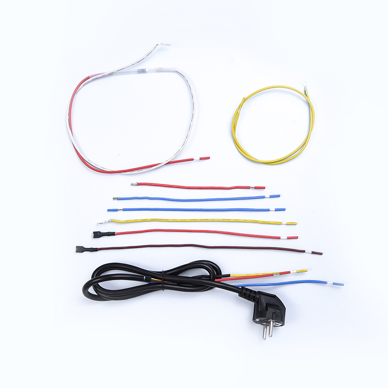
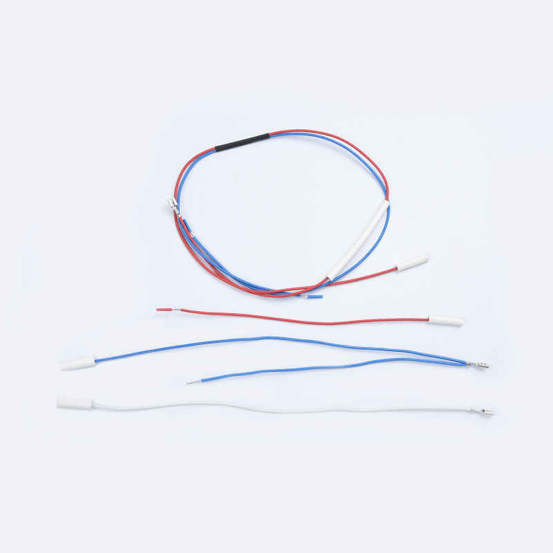
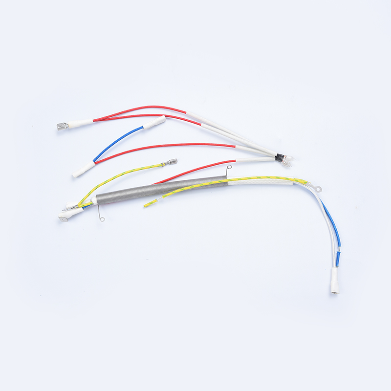
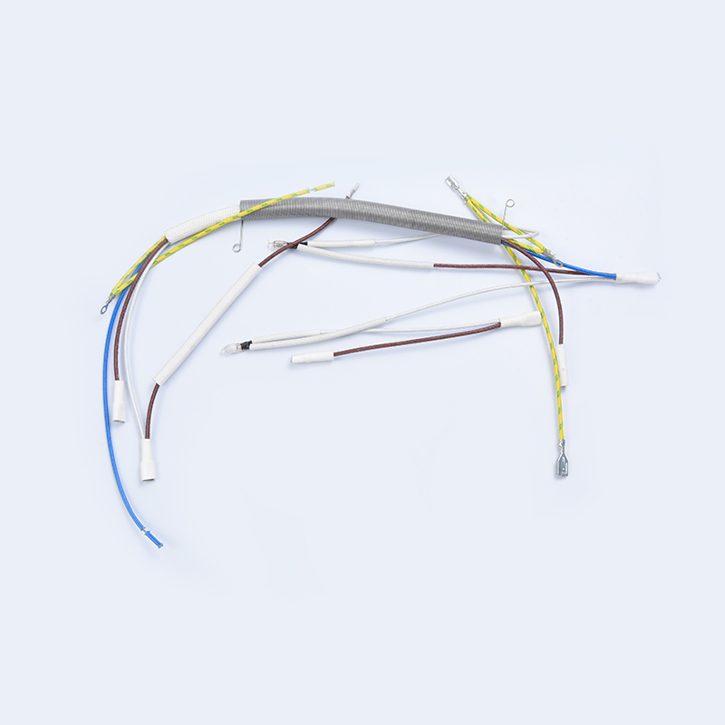
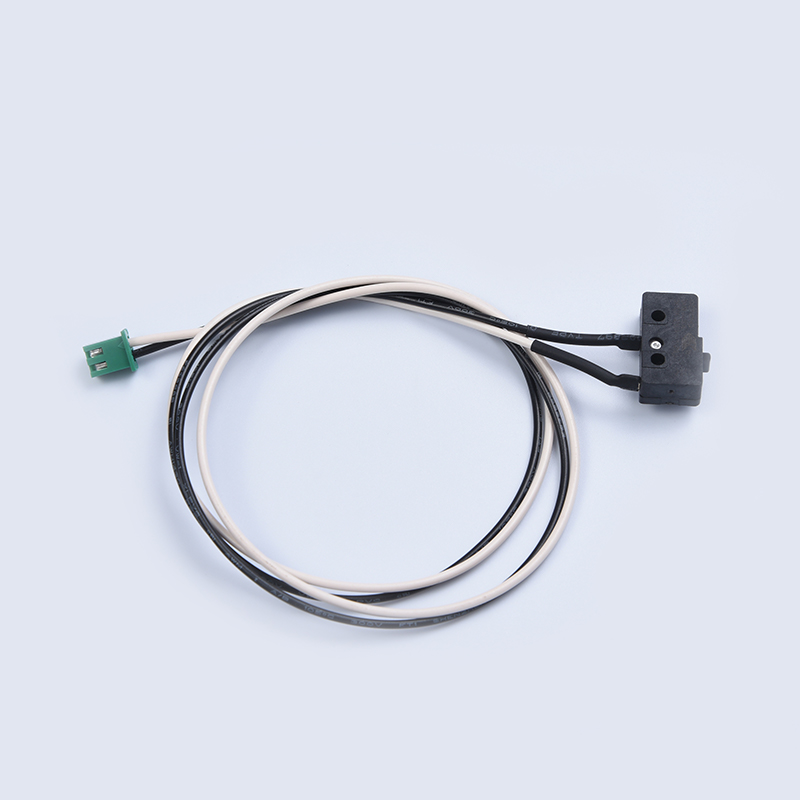 Washing Machine Wiring Harness for Safe Appliance RepairThis component connects motors, pumps, heaters, and sensors, with high-temperature and waterproof insulation. Its clear wire identification helps technicians avoid energizing the wrong circuit.View Product →
The same thinking applies to a room heater, where high current makes clear identification a safety issue rather than a convenience.
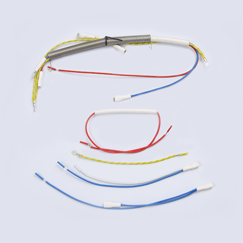
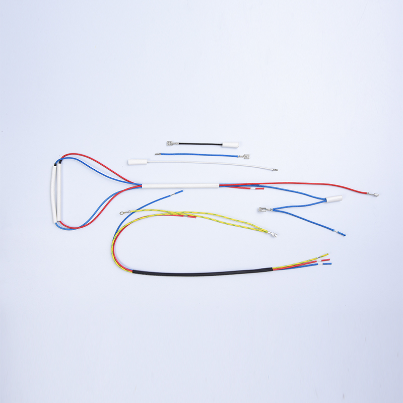 Heater Wiring Harness Category for High-Current ApplicationsThis category lists customizable heater harnesses featuring high-temperature silicone and PTFE insulation, UL and CE compliance, and reliable power distribution for safe servicing.View Product →
And even in a simple electric kettle, the live, neutral, and ground leads must be unmistakable so that the appliance can be serviced without guesswork.
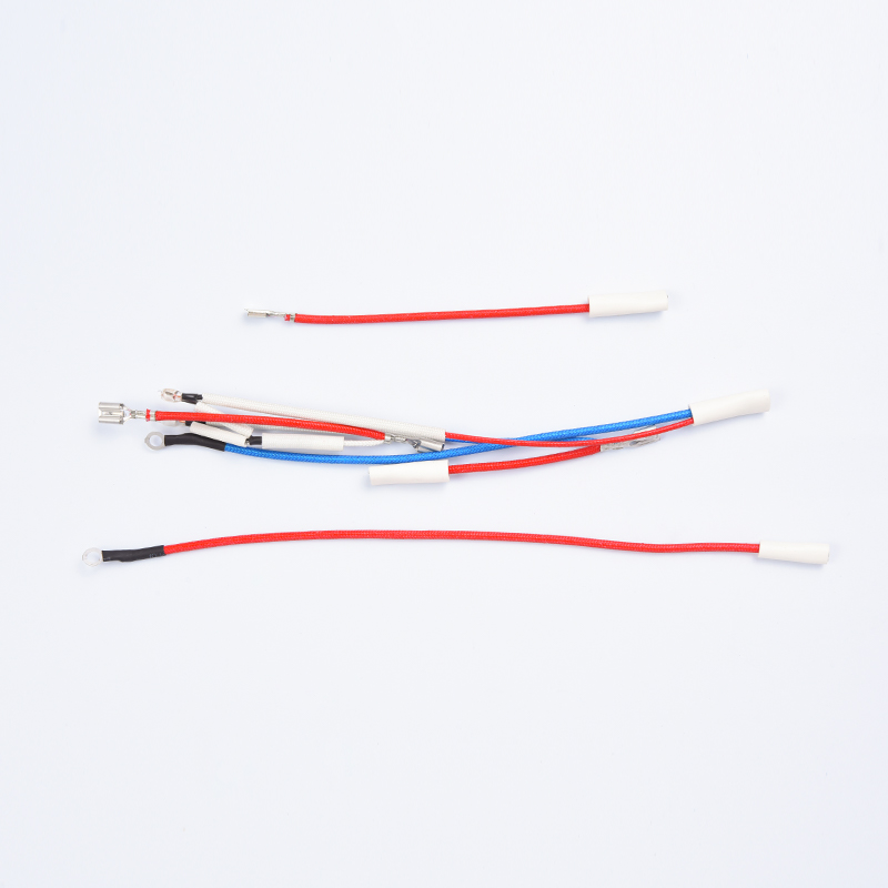
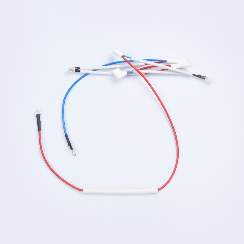 Comprehensive Home Appliance Wiring Harness CategoriesCovering kitchen and environmental appliances, NTC sensors, and center covers, this range supports workshops and production lines with clearly identified wires for safe installation.View Product →
Whether you are replacing an alternator in a workshop or installing a harness on a production line, the fundamental habit is the same: know every wire's function before you connect it.
Identifying alternator wires comes down to three steps: check the wiring diagram and terminal labels, use wire color and thickness as a starting point, and verify every conductor with a multimeter. Follow that order and you can connect an alternator with confidence. And when you need a replacement harness for any electrical system, browsing the range at a specialist wire harness factory will save you the same kind of guesswork.