+86-0574-63316601


 中文简体
中文简体Content
- 1 The NTC Temperature Sensor Is the Thermal Brain of Every Induction Cooker
- 2 How NTC Thermistors Work Inside an Induction Cooker
- 3 Key Specifications to Understand When Selecting an NTC Sensor
- 4 Packaging and Mounting Formats for Induction Cooker NTC Sensors
- 5 NTC Sensor Role in Induction Cooker Control and Safety Logic
- 6 Common Failure Modes and Fault Diagnosis
- 7 Replacement Guidelines: Getting the Right NTC Sensor
- 8 NTC vs. Other Temperature Sensing Technologies in Induction Cookers
- 9 Design Considerations for Engineers and Product Developers
The NTC Temperature Sensor Is the Thermal Brain of Every Induction Cooker
An NTC (Negative Temperature Coefficient) thermistor is the primary temperature-sensing component inside every induction cooker. Its job is to monitor the temperature of the glass-ceramic cooking surface and the IGBT power module in real time, feeding continuous resistance readings to the microcontroller so it can regulate output power, trigger overheat protection, and cut power when a pot is removed. Without a correctly functioning NTC sensor, an induction cooker cannot safely control its own heat output — it will either shut down immediately or, more dangerously, run without thermal limits.
The defining characteristic of an NTC thermistor is that its electrical resistance decreases as temperature rises — the opposite of a standard resistor. In a typical induction cooker application, the NTC sensor might read 100 kΩ at 25°C and drop to roughly 1.5 kΩ at 150°C, giving the control circuit a wide, easily measurable signal range across the entire cooking temperature span.
How NTC Thermistors Work Inside an Induction Cooker
Understanding the operating principle helps engineers specify the right sensor and helps technicians diagnose failures accurately.
The Resistance-Temperature Relationship
NTC thermistors are made from sintered metal oxide semiconductors — typically mixtures of manganese, nickel, cobalt, or copper oxides. As temperature increases, more charge carriers are freed in the semiconductor lattice, dramatically reducing resistance. This relationship follows the Steinhart-Hart equation or, for simpler implementations, the Beta (β) equation:
R(T) = R₀ × e^[β × (1/T − 1/T₀)]
where R₀ is resistance at reference temperature T₀ (usually 25°C = 298.15 K), T is the actual temperature in Kelvin, and β is the material constant — typically 3,000–4,500 K for induction cooker NTC sensors. A higher β value means a steeper resistance drop per degree, giving greater sensitivity but also requiring more precise ADC (analog-to-digital converter) resolution in the MCU.
The Voltage Divider Circuit
The NTC thermistor is almost always wired in a resistor voltage divider with a fixed reference resistor. The MCU's ADC samples the mid-point voltage, which shifts predictably as the NTC resistance changes with temperature. A typical circuit uses a 10 kΩ or 100 kΩ fixed resistor paired with the NTC, referenced to 3.3 V or 5 V. The MCU firmware converts the ADC reading to resistance, then to temperature using a lookup table or the β equation — a calculation completed every 100–500 ms during operation.
Dual Sensing Roles in One Appliance
Most induction cookers use at least two NTC sensors serving distinct functions:
- Ceramic surface sensor: Mounted directly beneath the glass-ceramic plate, it monitors cookware and surface temperature. Typical operating range: 25°C to 280°C, with an overheat cutoff trigger around 240–260°C.
- IGBT / heatsink sensor: Positioned on or near the IGBT transistor and its heatsink, it prevents the power switching module from exceeding its thermal limit — typically 85–100°C junction temperature. Exceeding this threshold causes the MCU to reduce power or shut down within milliseconds.
Key Specifications to Understand When Selecting an NTC Sensor
Not all NTC thermistors are interchangeable. Substituting a sensor with different specifications will cause the cooker's temperature readings to be systematically wrong — potentially by tens of degrees — leading to nuisance shutdowns, inability to reach target temperatures, or, in the worst case, undetected overheating.
| Specification | Typical Value (Induction Cooker) | Why It Matters |
|---|---|---|
| Nominal resistance (R25) | 10 kΩ, 47 kΩ, or 100 kΩ at 25°C | Must match the MCU firmware lookup table; wrong R25 shifts all readings |
| Beta value (β) | 3,435 K / 3,950 K / 4,050 K | Determines temperature sensitivity; mismatch causes non-linear reading error |
| Resistance tolerance | ±1% or ±2% at 25°C | Tighter tolerance = more accurate temperature reading from first use |
| Operating temperature range | −20°C to +300°C (surface); −20°C to +125°C (IGBT) | Sensor must survive maximum possible exposure without drift or failure |
| Thermal time constant | 5–15 seconds (surface); 2–8 seconds (IGBT) | Slower response means the sensor lags behind real temperature; critical for fast overheat detection |
| Insulation resistance | ≥100 MΩ at 500 V DC | Prevents leakage current causing false readings in high-voltage proximity |
| Lead wire length and gauge | 100–500 mm, 24–28 AWG | Must reach MCU without adding significant lead resistance that offsets R25 |
Packaging and Mounting Formats for Induction Cooker NTC Sensors
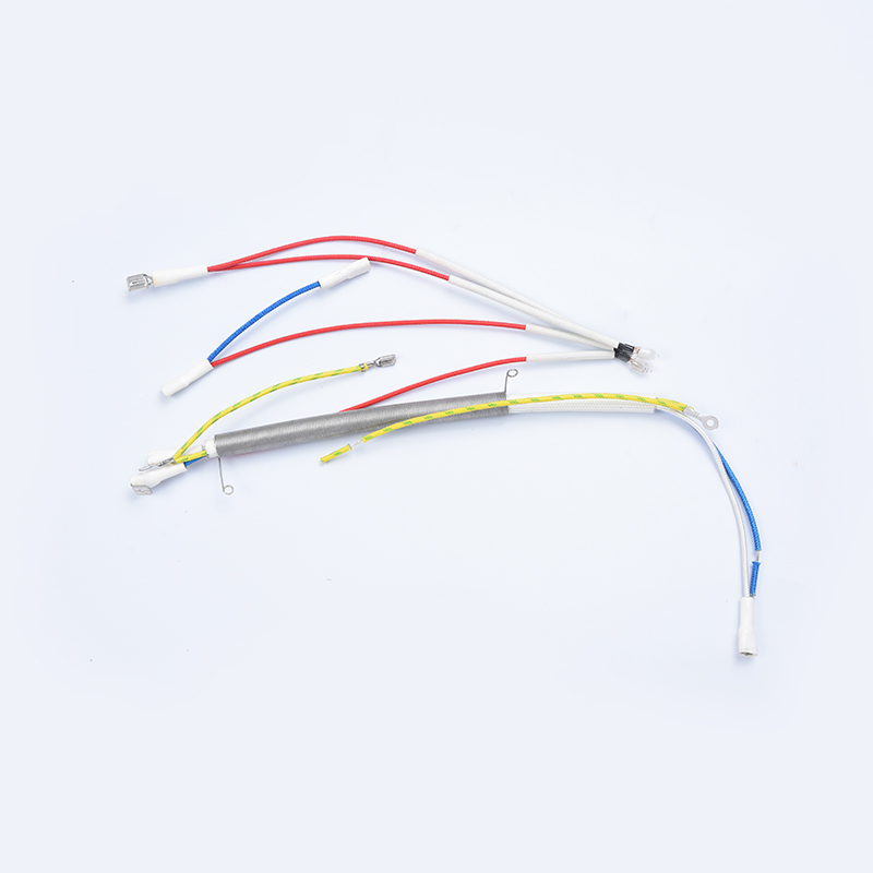
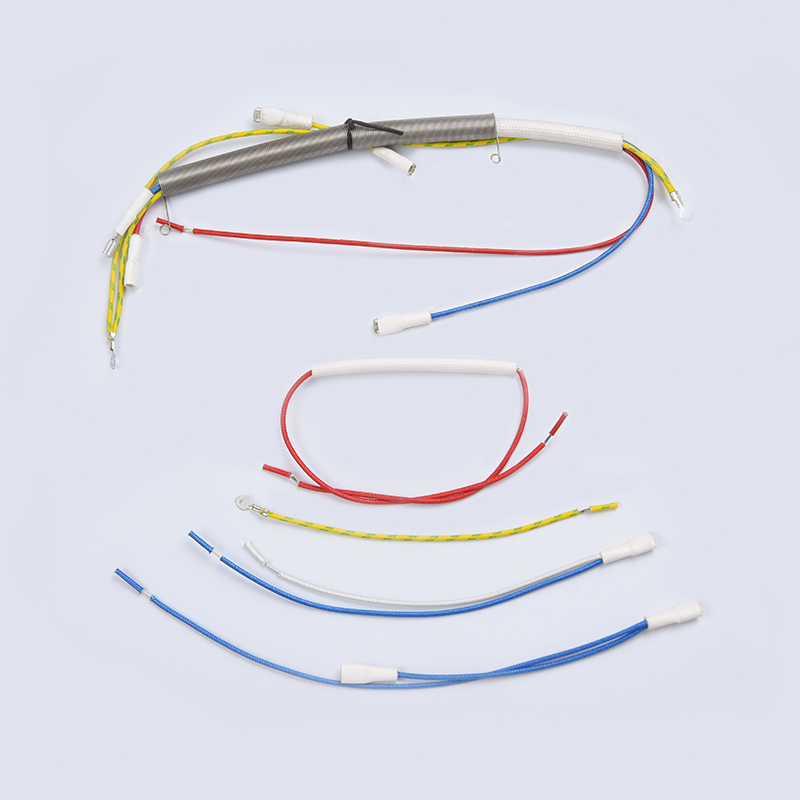
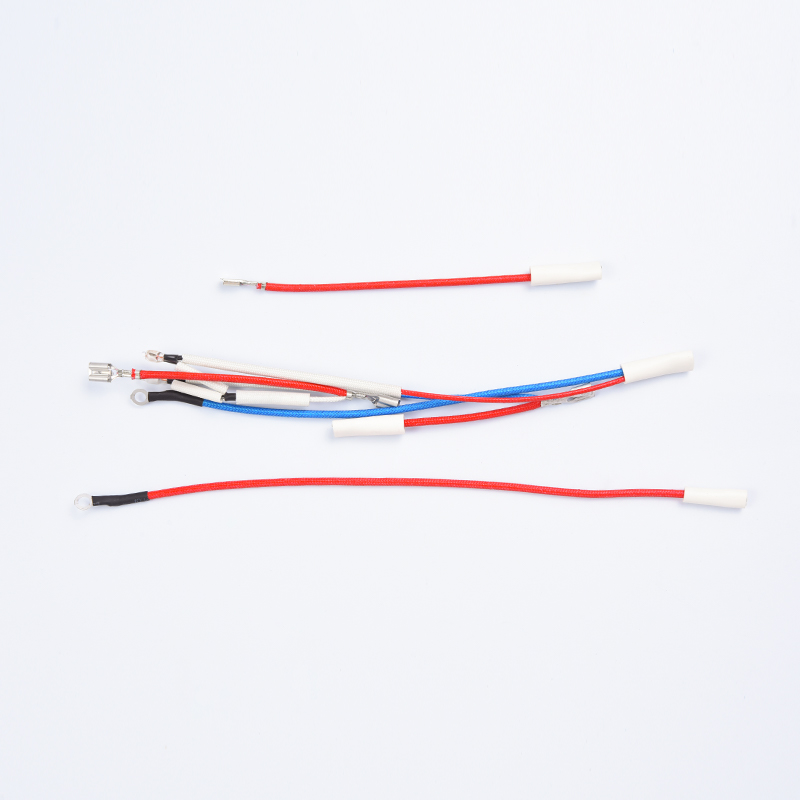
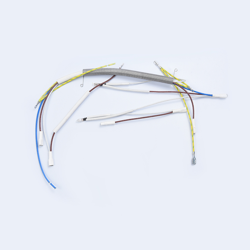
The thermistor element itself is tiny — often a 1–3 mm bead — but the packaging around it determines how well it contacts the surface being measured, how quickly it responds, and how long it survives the mechanical and thermal stresses of daily cooking use.
Spring-Loaded Surface Probe (Most Common for Ceramic Plate)
The NTC bead is encapsulated in a metal cap — usually stainless steel or aluminum — attached to a spring bracket that holds it in constant contact with the underside of the glass-ceramic cooking surface. The spring ensures contact is maintained despite thermal expansion and vibration. Thermal grease or a thin ceramic pad between the cap and the glass improves conductivity and reduces thermal time constant from 12 seconds to approximately 5–7 seconds in well-designed assemblies.
Clamp-On IGBT Sensor
For IGBT temperature monitoring, the NTC is typically mounted in a small plastic housing that clips or screws directly onto the IGBT heatsink. The housing keeps the sensor in firm contact with the aluminum heatsink surface while electrically isolating the thermistor leads from the high-voltage components nearby. Some designs use a push-in clip with an integrated thermal pad, allowing replacement without tools — important for service technicians.
Bare-Bead Epoxy-Encapsulated Sensors
Lower-cost induction cookers sometimes use bare NTC beads coated in high-temperature epoxy, glued directly to a PCB-mounted location near the coil. Response time is slower and long-term stability is lower than spring-probe designs, but the cost is significantly reduced. These are more common in sub-$50 appliances and are a frequent source of field failures after 2–3 years of use.
SMD (Surface-Mount) NTC for Board-Level Temperature Monitoring
Some designs include a small SMD NTC thermistor directly on the main PCB to monitor ambient temperature inside the appliance enclosure. This helps the firmware compensate for elevated ambient conditions — for instance, reducing maximum IGBT power when the enclosure internal temperature already exceeds 50°C, preventing cumulative thermal stress.
NTC Sensor Role in Induction Cooker Control and Safety Logic
The NTC thermistor feeds data to every significant safety and control function in a modern induction cooker. Understanding these functions explains why sensor accuracy is so consequential.
Power Level Regulation
When a user sets a specific temperature (e.g., 160°C for deep frying), the MCU uses the NTC surface sensor reading in a closed-loop control algorithm — typically a PID (proportional-integral-derivative) controller — to modulate the IGBT switching duty cycle. As the surface approaches the target, power is progressively reduced to avoid overshoot. A sensor error of just ±5°C can cause the actual surface temperature to overshoot the setpoint by 15–25°C due to thermal lag in the glass-ceramic plate.
Overheat Protection Cutoff
The surface NTC triggers an immediate power cutoff if temperature exceeds a programmed threshold — typically 240°C to 260°C depending on the manufacturer. This protects against cookware boiling dry, oil reaching its smoke point, or an empty pan being left on an active burner. The cooker typically displays an error code (E1, E2, or similar) and requires the surface to cool below approximately 80°C before it will restart.
Pan Detection Assistance
Pan detection primarily relies on the induction coil's resonant frequency change when a ferromagnetic pan is placed on the surface. However, the NTC surface sensor provides a secondary check: if power is applied but the surface temperature does not rise at the expected rate within 3–5 seconds, the MCU interprets this as no pan present and shuts down. A faulty NTC that reads constant low temperature can cause repeated false "no pan" shutdowns even with a valid cookware piece correctly positioned.
IGBT Thermal Derating
The IGBT NTC enables dynamic power derating — reducing the output power progressively as IGBT temperature rises, rather than waiting for a hard cutoff. For example, full power (2,000 W) might be allowed up to 70°C heatsink temperature; above 70°C, power ramps down linearly to 50% at 85°C; above 90°C, the unit shuts down. This graduated response extends IGBT service life significantly compared to simple on/off thermal switches.
Soup and Milk Boil-Over Prevention
Premium induction cookers use the NTC surface sensor to detect the rapid temperature fluctuation that occurs when a liquid begins boiling. The firmware monitors the rate of temperature change (dT/dt); when the derivative spikes — indicating surface contact has been broken momentarily by vigorous bubbling — the MCU reduces power for a short interval to prevent boil-over. This feature requires a sensor with a thermal time constant below 8 seconds to detect the signal fast enough to be useful.
Common Failure Modes and Fault Diagnosis
NTC sensor failures account for a significant proportion of induction cooker field returns. Most failures fall into a small number of repeatable patterns, each with a distinct diagnosis method.
Open Circuit (Resistance → Infinity)
A broken lead wire or fractured thermistor element causes infinite resistance. The MCU interprets this as an extremely low temperature and typically responds with immediate shutdown and an error code (commonly E0 or E3 on Chinese-manufactured units). Measure the sensor with a multimeter at room temperature — a reading of OL (overload/open) confirms the fault. This is the most common failure mode in units subjected to vibration or repeated thermal cycling.
Short Circuit (Resistance → Near Zero)
Insulation breakdown — from chemical contamination, moisture ingress, or physical damage to the lead wire — can cause the two thermistor leads to short together. The MCU sees a near-zero resistance reading and interprets it as an extremely high temperature, triggering overheat cutoff immediately at startup. The cooker will turn on briefly then cut out with an overheat error, even when cold.
Resistance Drift
After years of exposure to high temperatures (>200°C repeatedly), the thermistor material can drift — its resistance at a given temperature shifts from the original calibration curve. A sensor that originally read 2.5 kΩ at 150°C might drift to 3.2 kΩ, causing the MCU to believe the surface is 130°C when it is actually 150°C. This allows actual temperatures to exceed the safety threshold before the cutoff triggers. Drift-related failures are the most dangerous because they produce no error code — the cooker appears to function normally.
Poor Thermal Contact
A spring-probe sensor that has lost spring tension, or an IGBT sensor whose clip has bent away from the heatsink, creates an air gap between the sensor and the measured surface. The sensor reads significantly lower than the actual surface temperature — often by 30–60°C — causing the cooker to apply more power than it should. Visually inspect spring tension and clip fit before condemning the sensor electrically.
Step-by-Step NTC Sensor Diagnosis
- Disconnect the sensor connector from the PCB. Measure resistance at room temperature (aim for 20–25°C). Compare to the sensor's R25 specification — should be within ±5% for a healthy sensor.
- Heat the sensor gently with a heat gun to approximately 50°C (verify with a calibrated thermometer). Resistance should drop noticeably — roughly 50–60% of R25 for a β ≈ 3,950 K sensor.
- Continue heating to 100°C. Cross-reference the measured resistance against the manufacturer's R-T table. A deviation of more than ±3% at this point indicates drift requiring replacement.
- Inspect lead wires for cracking, discoloration, or abrasion. Flex each wire gently while monitoring resistance — intermittent open circuits will show as resistance spikes.
- Inspect the mounting spring or clip. Press the probe firmly against a flat surface and verify it returns to position with consistent spring force. Replace the assembly if the spring is deformed.
Replacement Guidelines: Getting the Right NTC Sensor
Replacing an induction cooker NTC sensor with an incorrect part is one of the most common appliance repair mistakes. The sensor may physically fit and electrically connect, but if the R25 or β values differ from the original, the cooker's temperature readings will be wrong from the first use.
How to Identify the Correct Replacement
- Check the service manual first. Major brands (Midea, Philips, Panasonic, De'Longhi, Electrolux) publish service manuals that list the NTC part number and its R25/β values explicitly.
- Read the original sensor's markings. Many sensors have the R25 value printed on the body or label (e.g., "10K," "47K," "100K"). β values are less often marked but may be present as a 4-digit number (e.g., "3950").
- Measure the original sensor at two known temperatures to calculate its β value before discarding it, even if it has failed electrically — the β can often be derived from an R-T table if R25 is known.
- Match the physical format exactly: spring-probe assembly dimensions, lead wire length, connector type, and lead wire insulation material (silicone is required for surface probes; PVC degrades above 105°C).
Widely Used NTC Values in Induction Cookers
| R25 Value | Common β Value | Typical Brand / Application | R at 100°C (approx.) |
|---|---|---|---|
| 10 kΩ | 3,435 K | Budget-range Chinese OEM units, IGBT monitoring | ~678 Ω |
| 10 kΩ | 3,950 K | Midea, Galanz, Joyoung mid-range models | ~549 Ω |
| 47 kΩ | 4,050 K | Panasonic, some Philips surface probes | ~2.4 kΩ |
| 100 kΩ | 3,950 K | European induction hob OEMs (Electrolux, Bosch platforms) | ~5.5 kΩ |
| 100 kΩ | 4,150 K | High-precision smart cookers, induction woks | ~4.7 kΩ |
NTC vs. Other Temperature Sensing Technologies in Induction Cookers
NTC thermistors dominate induction cooker design, but understanding why — and where alternatives are used — provides useful context for engineers evaluating sensor options.
| Sensor Type | Temperature Range | Accuracy | Cost | Induction Cooker Use |
|---|---|---|---|---|
| NTC Thermistor | −50°C to +300°C | ±1–3°C (calibrated) | Very low ($0.10–$1.50) | Primary surface and IGBT sensing — universal |
| PT100 / PT1000 RTD | −200°C to +600°C | ±0.3°C | Medium ($2–$15) | Rare; used in professional/laboratory induction units |
| Type K Thermocouple | −200°C to +1,260°C | ±2.2°C or ±0.75% | Low–medium ($1–$10) | Rare in consumer units; requires cold junction compensation circuit |
| Infrared (non-contact) | −20°C to +500°C | ±2–5°C | High ($3–$20) | Emerging in premium smart cookers; measures cookware directly |
The NTC thermistor's dominance comes down to a combination of very low cost, adequate accuracy for the application, simple analog interface with any MCU, and proven long-term reliability when correctly specified. PT100 RTDs deliver superior accuracy but require a precision constant-current source and a more complex signal conditioning circuit that adds cost and PCB space. For the temperature range and precision requirements of consumer induction cooking, the NTC remains the optimal choice.
Design Considerations for Engineers and Product Developers
For engineers designing or redesigning induction cooker temperature sensing circuits, several practical decisions significantly affect measurement quality and product reliability.
Choosing the Right Reference Resistor Value
The fixed resistor in the voltage divider should be chosen to maximize ADC resolution at the most critical part of the temperature range. For a surface NTC with R25 = 100 kΩ and β = 3,950 K, the most critical monitoring range is 150–250°C — where the NTC resistance is approximately 1.5–5.5 kΩ. Setting the reference resistor to 10 kΩ places the voltage divider midpoint in a high-sensitivity region across this range, extracting maximum signal change per degree from the ADC's input span.
Self-Heating Error
Current flowing through the NTC for measurement purposes generates heat within the thermistor element itself — raising its temperature above the surface it is supposed to measure. With a 5 V supply and a 100 kΩ NTC, the power dissipated in the sensor is only about 0.25 µW — negligible. However, with a 10 kΩ NTC and 5 V supply, dissipation can reach 2.5 mW, enough to cause a self-heating error of 0.5–2°C in poorly ventilated probe assemblies. Using the smallest practical supply voltage (3.3 V in modern MCU designs) and a higher nominal resistance sensor mitigates this effect.
EMI Shielding of Sensor Leads
Induction cookers generate strong electromagnetic fields at 20–100 kHz from the coil. Unshielded NTC lead wires running near the coil can pick up this field as noise on the low-level analog signal feeding the ADC. Best practice is to use twisted-pair or shielded cable for NTC leads longer than 150 mm, add a 100 nF ceramic capacitor across the NTC terminals at the PCB, and route the analog signal trace away from high-current coil driver lines.
Firmware Sensor Fault Detection
Robust induction cooker firmware should continuously validate NTC readings rather than blindly trusting them. Practical checks include:
- ADC reading below minimum threshold (near zero) → open circuit detected → shutdown with error code.
- ADC reading above maximum threshold (near supply rail) → short circuit detected → shutdown with error code.
- Temperature rise rate slower than minimum expected during startup → probable poor thermal contact → warning flag.
- Surface temperature reading more than 40°C above IGBT temperature during continuous high-power operation → cross-check anomaly → log for service review.