+86-0574-63316601


 中文简体
中文简体Content
- 1 What a Schematic Shows, and What It Deliberately Leaves Out
- 2 The Symbol Vocabulary That Does Most of the Work
- 3 Junctions, Nets, and the Dot Rule
- 4 Reference Designators and Values
- 5 A Reading Routine That Works on Any Drawing
- 6 Worked Example: Tracing a Heating Appliance Circuit
- 7 Mistakes That Catch Out New Readers
- 8 From the Drawing to the Finished Assembly
Anyone who opens an appliance project drawing for the first time meets the same wall: pages of small symbols, lines crossing in every direction, and labels like K1-2 or TH1 that explain nothing on their own. The good news is that reading electrical schematic drawings is not a talent reserved for electrical engineers. It comes down to four habits: building a core symbol vocabulary, understanding how lines and junctions represent connections, decoding reference designators and values, and following a consistent tracing routine. Once those habits are in place, a schematic stops looking like noise and starts reading like a story, in which power enters the circuit, gets protected and switched, does useful work in a load, and returns to the source.
This skill matters well beyond the engineering department. Procurement teams reviewing supplier drawings, quality staff tracing a failure report, and maintenance technicians diagnosing a faulty appliance all read schematics faster and with fewer errors when they apply the same fundamentals.
What a Schematic Shows, and What It Deliberately Leaves Out
Start with the most important conclusion: a schematic diagram describes electrical logic, not physical geography. Two components drawn on opposite corners of a sheet may be electrically in series, while two symbols sitting side by side may belong to completely separate circuits. The drawing's job is to show how current flows and how signals interact, not where parts sit on a PCB or inside a housing.
Electrical documentation usually includes three related but distinct drawing types. A schematic diagram shows circuit function with standardized symbols. A wiring diagram shows the physical routing and connections between real components, including cable paths and connector positions. A single-line diagram simplifies polyphase systems into one line per group of conductors, which is common in power distribution rather than appliance design. On the appliance side, the schematic defines the circuit, the wiring diagram maps it onto real cables and terminals, and the finished part built from that map is what a wiring harness actually is. Knowing which document you are holding is the first step in reading it correctly.
The Symbol Vocabulary That Does Most of the Work
Here is the encouraging part: roughly twenty symbols cover the majority of household appliance schematics. You do not need to memorize an entire library before your first useful read. Focus on six functional groups, summarized below.
| Symbol group | Typical members | What to check when reading |
|---|---|---|
| Power and reference | AC source, battery, ground and neutral nodes | Where supply enters the sheet and which node serves as the voltage reference |
| Passive components | Resistors, capacitors, inductors, transformers | Value, rating and polarity printed beside each designator |
| Switches and relays | Toggle switches, push buttons, relay contacts | Contacts are drawn in their rest state, not their working state |
| Protection devices | Fuses, thermal cutoffs, varistors, thermistors | The series position shows exactly what each device protects |
| Loads | Motors, heating elements, lamps, pumps | The endpoint of every power path and the component that consumes current |
| Connections | Junction dots, terminals, off-page connectors | A dot confirms a joint; crossing lines without a dot never touch |
One symbol deserves special attention in appliance work: the thermistor. On schematics for kettles, ovens, heaters, and coffee machines, the NTC thermistor appears as a resistor symbol with a bent line through it, often flagged with a temperature marker and labeled TH or RT. Its resistance falls as temperature rises, which is precisely how a control board knows when water has boiled or when a heating chamber has reached setpoint. Understanding how NTC temperature sensors behave in a circuit turns that one small symbol into a reliable reading anchor, because you can immediately identify the sensing branch of any heating appliance.
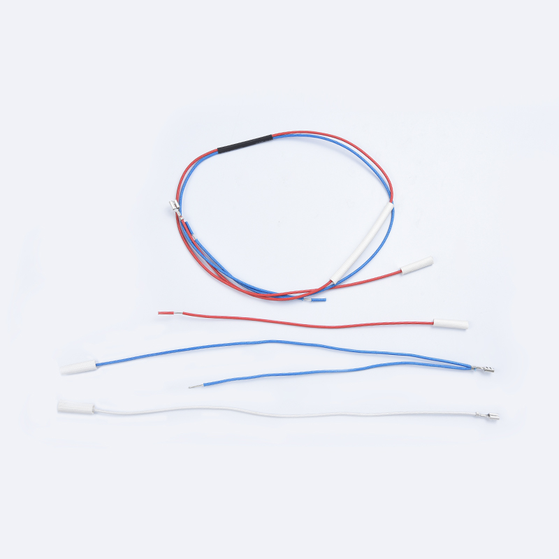
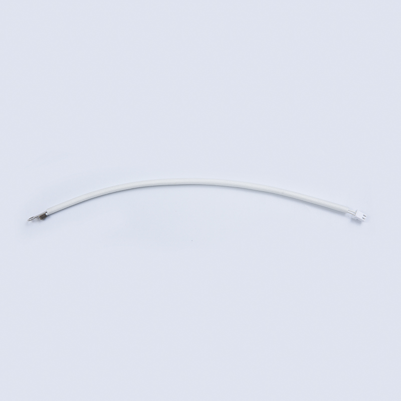 NTC Temperature Sensors for Heating AppliancesNTC thermistor symbols mark the sensing branch of kettles, ovens, and heaters, where resistance falls as temperature rises. These sensors give control boards the temperature feedback needed to detect boil or setpoint conditions.View Product →
Junctions, Nets, and the Dot Rule
Misreading connections is the single most common beginner error, and one convention prevents most of it. Wherever a filled dot appears at the intersection of two lines, those wires are electrically joined. Where two lines simply cross without a dot, they pass over each other with no connection. T-shaped junctions are normally connected even without a dot, but practice varies between drafting tools, so treat the legend as the authority.
Large drawings also use net labels to keep lines tidy. Instead of dragging a wire across three sheets, the drafter places the same name, such as GND, L, N, or VCC, at both ends, and everything sharing a name is one electrical node. Off-page connectors work the same way, signaling that a path continues on another sheet, usually marked with a sheet number or arrow. Treat these labels as real wire: if you see the same label twice, those points are connected whether or not a line is drawn between them.
Reference Designators and Values
Every symbol on a professional drawing carries a reference designator, a short code that names the component class and its instance number. The common prefixes are worth learning as a set:
- R for resistors, C for capacitors, L for inductors
- D for diodes and LEDs, Q for transistors, U for integrated circuits
- K for relays and contactors, F for fuses, T for transformers
- M for motors, SW or S for switches, TH or RT for thermistors
Values sit beside the designator. A resistor marked 10k is 10 kilohms; a capacitor marked 470uF/16V carries its capacitance and a voltage rating you must respect. Watch polarity on electrolytic capacitors and diodes, because the symbol itself encodes orientation and installing the part backwards is a real failure mode.
Two subtleties separate new readers from experienced ones. First, parent-child components: a relay coil labeled K1 on the control page may operate contacts labeled K1-1 and K1-2 elsewhere, so the same relay appears in several places. Second, symbol standards differ. IEC and North American conventions draw contacts, grounds, and logic elements differently, so check which standard the drawing uses before interpreting any symbol.
A Reading Routine That Works on Any Drawing
Reading order matters more than reading speed. Experienced engineers rarely start at the first symbol; they start with structure. The following sequence works on schematics from a small kettle to an industrial controller.
- Read the title block and legend first: drawing number, revision, symbol standard, and sheet index. An outdated revision is a genuine safety risk.
- Locate the power entry: line and neutral, or DC positive and negative, plus the main fuse or breaker that heads the sheet.
- Divide the drawing into functional blocks: power supply, control, protection, sensing, and load.
- Trace the power path from source to load and back, confirming every protection device in series.
- Trace the control path: identify what switches the load, and what feedback, such as a thermistor or limit switch, influences that decision.
- Follow designators across pages, keeping parent-child relationships like relay coils and their contacts in view.
- Annotate as you go, and check anything unfamiliar against the component datasheet rather than guessing.
Worked Example: Tracing a Heating Appliance Circuit
Apply the routine to a simplified electric oven and the method becomes concrete. Power enters at L and N. Line first passes through fuse F1 and a thermal cutoff, then through the main switch to the heating element, which returns to N. That is the power path, and you can already state its protection chain: overcurrent at F1, overtemperature at the cutoff.
The control branch adds intelligence. A control board U1 derives its low-voltage supply from the mains, an NTC thermistor TH1 sits in the oven cavity and feeds a voltage divider into the board, and the board drives relay coil K1. When TH1 reports the cavity below setpoint, U1 energizes K1, and contact K1-1 closes to power the element. Read in that order, the schematic tells you exactly why an oven that never heats might have failed: an open fuse, an open thermal cutoff, a stuck K1 contact, or a thermistor reading out of range.
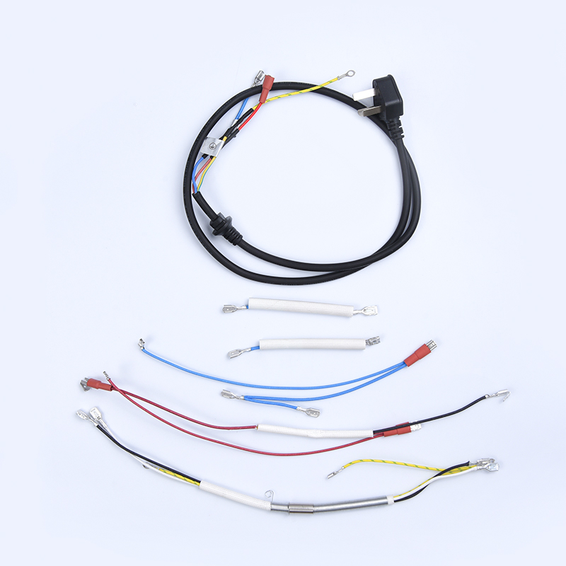
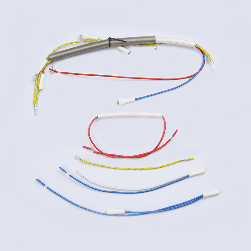
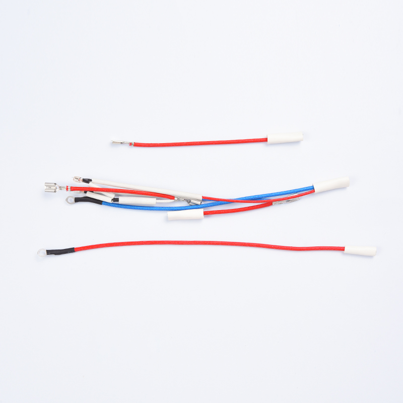
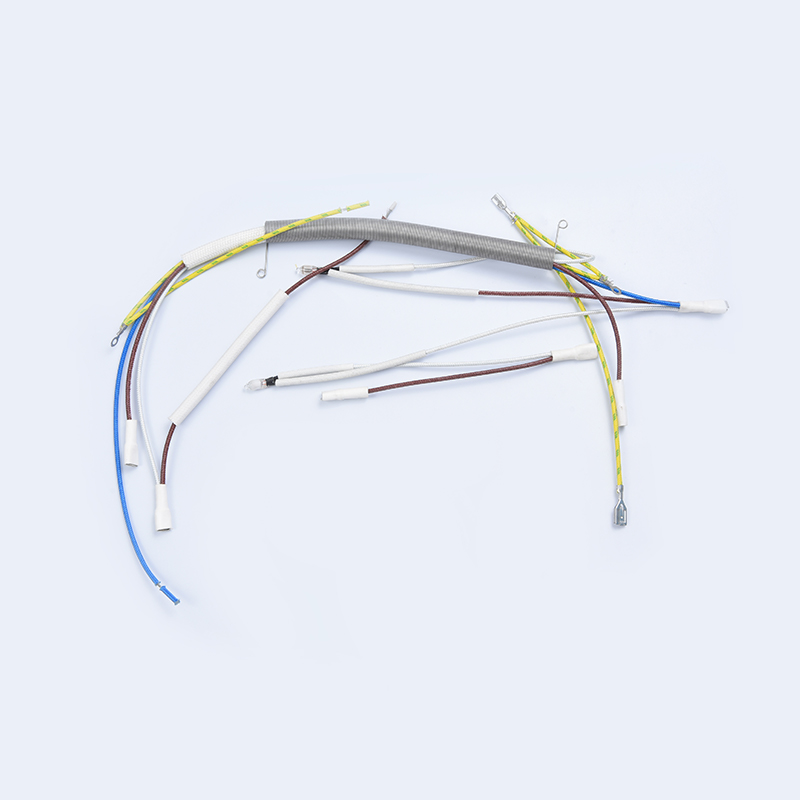
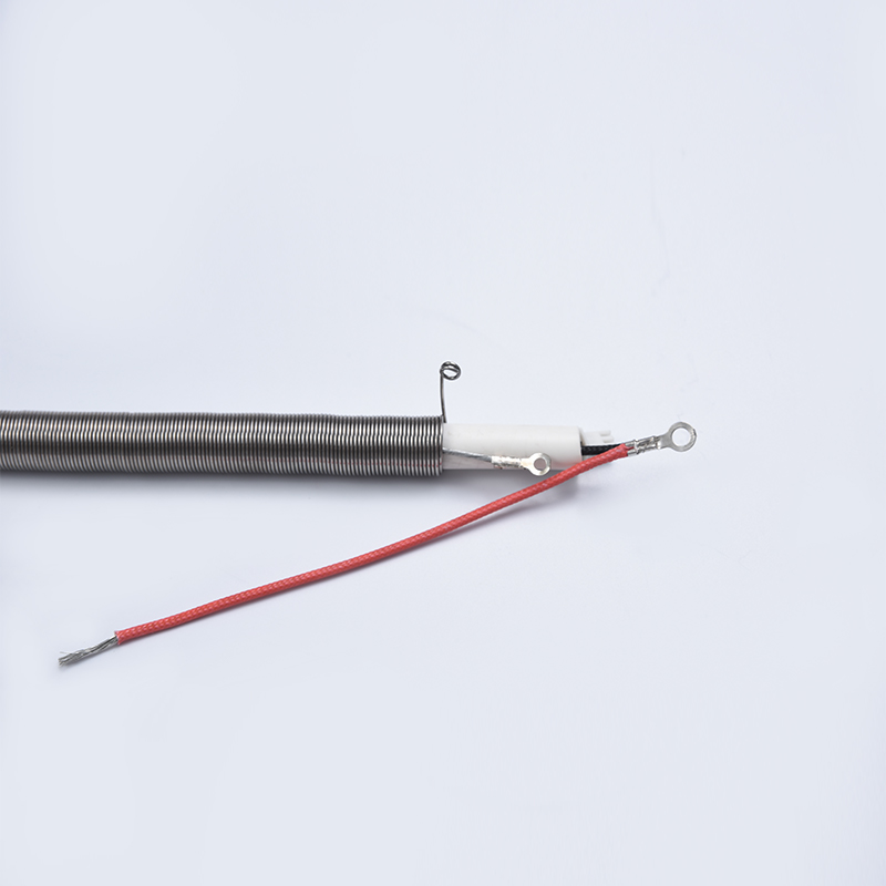
The final mental step is translating symbols into hardware. The element terminals, the relay contacts, the cutoff, and the thermistor all connect through bundled conductors and connectors, and the drawing set cross-references those routes. In production, that translation from schematic nets to routed, insulated, connectorized cables is exactly what a dedicated oven harness provides.
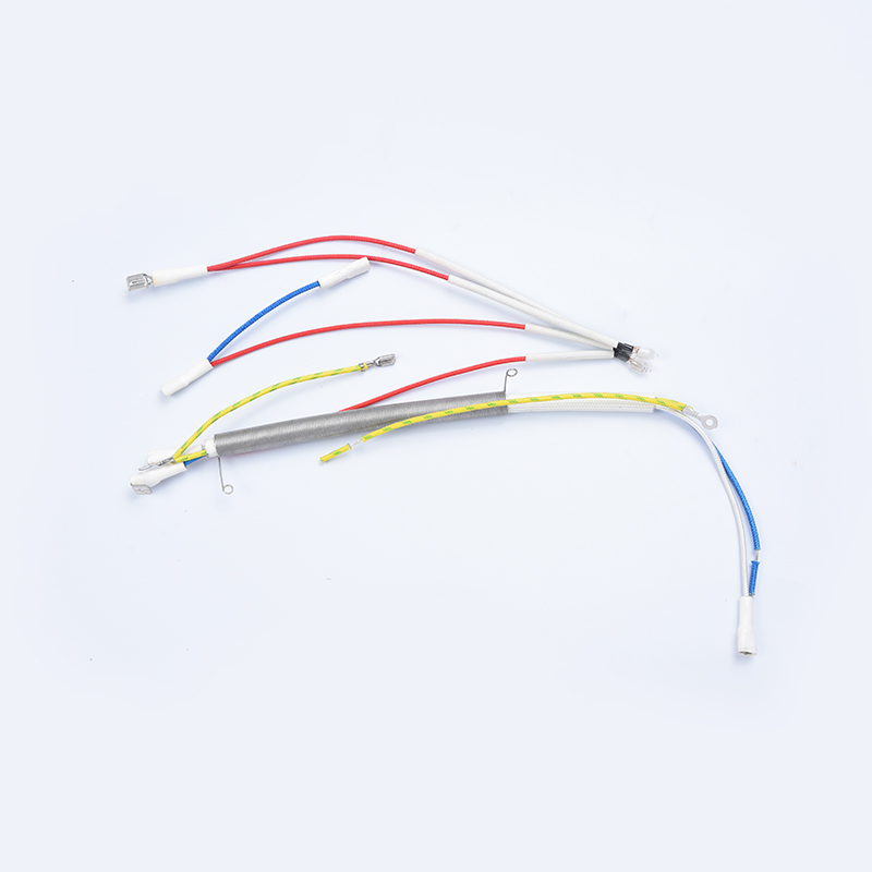
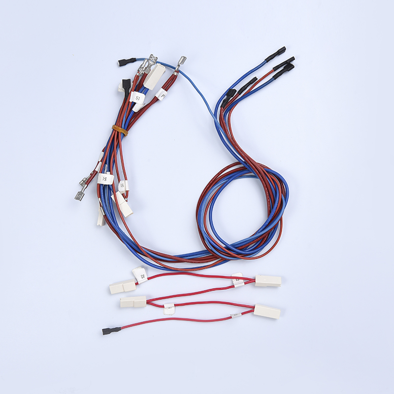 Electric Oven Wiring HarnessesOnce schematic symbols are translated into routed conductors, an oven wiring harness carries the element, relay, cutoff, and thermistor connections. Reviewing harness options here shows how schematic nets become insulated, connectorized cable assemblies.View Product →
Mistakes That Catch Out New Readers
Most schematic misreads fall into a handful of repeating traps. Checking for them deliberately shortens the learning curve considerably.
- Assuming symbol placement reflects physical location, which it never does on a schematic.
- Ignoring the dot rule and inventing connections at every line crossing.
- Reading relay contacts in their energized state, when drawings show the rest state by convention.
- Mixing IEC and ANSI symbol conventions within one interpretation.
- Skipping the legend and revision block, then analyzing a superseded drawing.
- Overlooking polarity marks on diodes and electrolytic capacitors.
From the Drawing to the Finished Assembly
Schematic literacy pays off most clearly during component sourcing. A buyer who can read the drawing can quote a harness accurately: wire gauge follows from load current, insulation class follows from the temperatures near heaters, connector selections come from the schematic's termination points, and the thermistor branch must match the control board's expected resistance curve. Those details are precisely where appliance manufacturers lose time when drawings and suppliers do not speak the same language.
It also changes the quality of conversations with a harness and sensor manufacturer. Instead of describing a part by appearance, you can reference nets, designators, and ratings directly, and the supplier can confirm feasibility against the same document. If you are preparing a new appliance project and want the schematic translated into a production-ready wiring solution, the engineering team behind these kitchen and environmental appliance assemblies reviews drawings and provides quotations through the standard request channel.
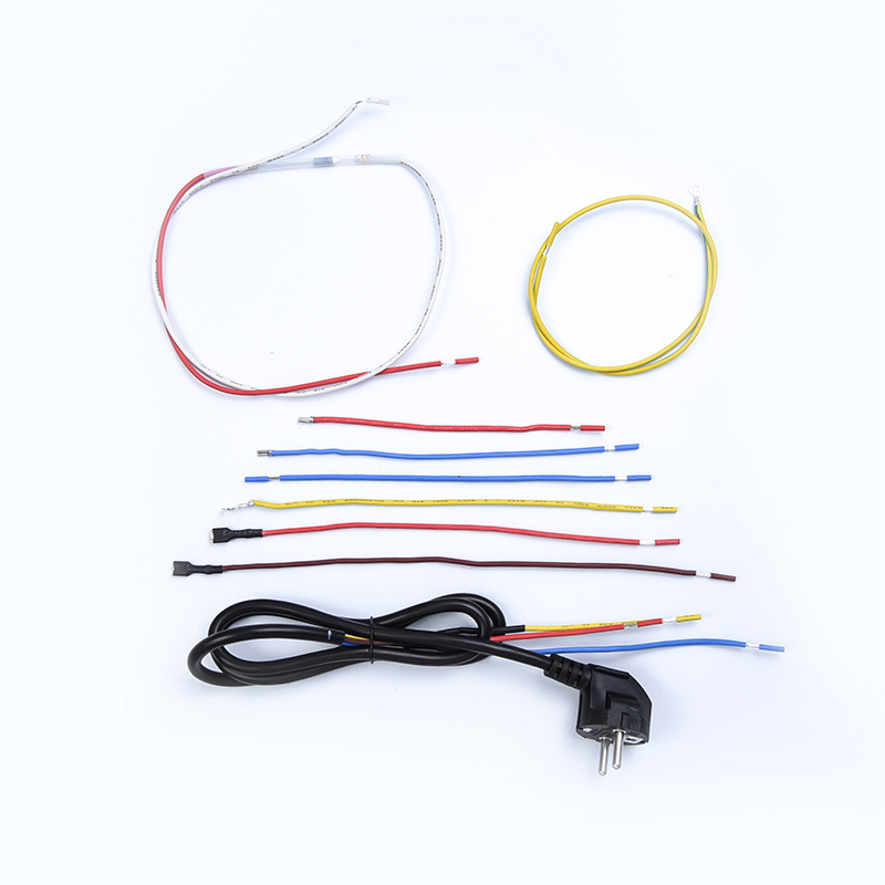
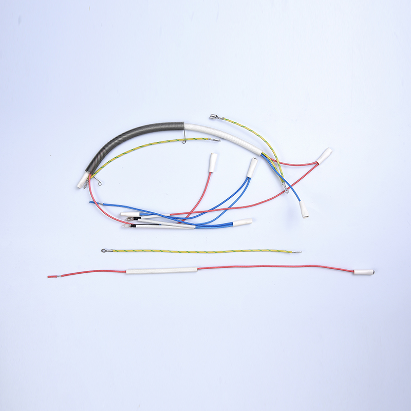 Kitchen Appliance Wiring Harness ManufacturingReading schematics fluently lets you discuss nets, designators, and ratings directly with a manufacturer. Kitchen appliance wiring harness suppliers can review your drawings and translate them into production-ready assemblies through standard quotation channels.View Product →