+86-0574-63316601


 中文简体
Content
- 1 Start with the sensor's resistance curve, not just the ohms
- 2 What to have on the bench
- 3 A safe, repeatable measurement
- 4 Reading the numbers without overconfidence
- 5 Three-wire sensors and real appliance conditions
- 6 Common mistakes that produce misleading readings
- 7 When the sensor passes but the appliance still misbehaves
- 8 A practical checklist for the next test
A temperature sensor usually gets noticed only when an appliance cooks too hot, brews too cold, or shuts down for no clear reason. Measuring resistance is often the fastest way to tell a failed sensor from a loose connector, a damaged wire, or a control board that is misreading a good signal. The test itself is simple, but the details matter: temperature, meter setup, connector condition, and the sensor's resistance curve all affect the number you see.
Start with the sensor's resistance curve, not just the ohms
Most appliance temperature sensors are NTC thermistors: negative temperature coefficient. Their resistance falls as temperature rises. A 10 kΩ NTC may read about 10 kΩ at 25 °C, roughly 33 kΩ near 0 °C, and less than 1 kΩ near 100 °C. Those are ballpark examples, not universal values. The datasheet's nominal resistance at a stated temperature, often 25 °C, and its B value define the curve. A PTC sensor behaves in the opposite direction, and an RTD has a much lower, more linear resistance change. If you are not sure which family you have, check the part marking and the appliance service information before judging a reading.
This background guide to what an NTC temperature sensor is explains the common bead, probe, and epoxy-coated forms. When replacement is likely, match the appliance type and resistance rating rather than buying the first look-alike part.
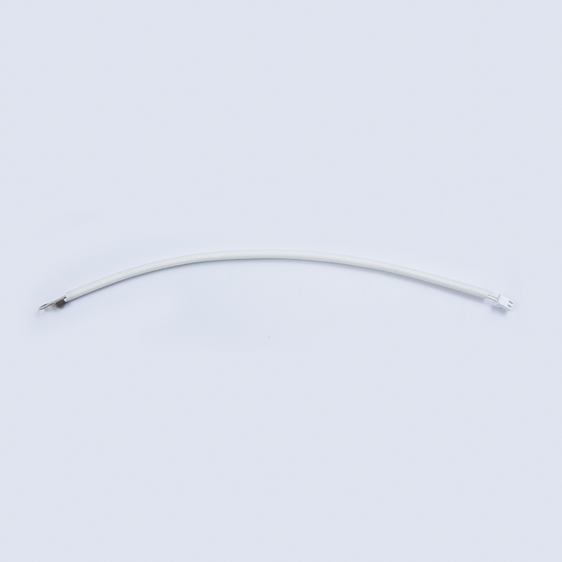 NTC Temperature Sensors for Appliance ControlBrowse application-specific NTC thermistor sensors for air fryers, coffee machines, kettles, and other appliances; match appliance type and resistance rating before replacement.View Product →
What to have on the bench
A clean setup prevents most false readings. Before you begin, gather:
- A digital multimeter with a resistance or ohms mode and a low test current setting; check the meter manual.
- The sensor datasheet, a resistance table, or service information with nominal resistance and B value.
- A reference thermometer for the actual sensor temperature.
- Insulated test clips or probes that will not short across closely spaced terminals.
- Isopropyl alcohol and a lint-free cloth for contaminated connectors.
- A notebook or photo record of part number, temperature, and reading.
Safety first: unplug the appliance, disconnect power, and let capacitors discharge before touching a sensor or connector. Never measure resistance on a live circuit. The meter supplies its own small test current, and external voltage will give meaningless results or damage the meter.
A safe, repeatable measurement
- Isolate and label. Unplug the appliance. Photograph connector orientation and mark any leads you may need to disconnect. Do not rely on memory.
- Identify the terminals. For a two-wire NTC, measure across the two sensor terminals. For a three-wire unit, find the common and signal leads from the datasheet or service guide. Three wires can mean two sensing elements, a shielded lead, or a shared connection; guessing leads to false conclusions.
- Check the meter. Select the appropriate resistance range or auto-range. Short the probe tips together and note the lead resistance; subtract it from low-ohm readings. Clean the probe tips.
- Bring the sensor to a known temperature. For an ambient check, let it sit in still air until stable. For a hot or cold check, use a temperature bath with a reference thermometer. Do not hold the sensor in your hand and expect a room-temperature value.
- Make a stable connection. Clip the probes to the terminals without touching the sensor body or each other. Wait for the display to settle. A rising or falling number often means thermal change, poor contact, or a meter range issue.
- Compare against the curve. Use a resistance table for the exact part and measured temperature. Allow the datasheet tolerance, and remember that a single reading does not prove the whole curve.
- Repeat at a second temperature. A reading that looks correct at 25 °C but barely changes when warmed is suspicious. The slope is often more informative than one number.
Reading the numbers without overconfidence
The table below is a practical sanity check, not a calibration certificate. It uses illustrative values for a common 10 kΩ NTC with a B25/50 value near 3950 K. Your sensor may use a different nominal resistance, B value, tolerance, or housing, so always confirm with its own data.
| Sensor temperature | Approximate resistance | What it usually means |
|---|---|---|
| 0 °C | About 33.6 kΩ | Cold-end reading; confirm the meter and probe contact |
| 25 °C | About 10 kΩ | Common nominal value, but only at the rated tolerance |
| 50 °C | About 3.6 kΩ | Warm reading; the sensor should be changing clearly |
| 75 °C | About 1.5 kΩ | Hotter reading; compare the slope, not just the number |
| 100 °C | About 0.70 kΩ | Near many cooking and heating ranges |
An open-circuit display, often shown as OL, suggests a broken element or lead. A near-zero reading suggests a short or a meter lead touching across terminals. A reading that drifts with a wiggle test points to a connector or cable problem. And a resistance that is plausible but far outside the expected tolerance at the measured temperature should be checked again before replacement.
Three-wire sensors and real appliance conditions
Three-wire sensors deserve extra care. In some assemblies, two wires serve one NTC element and the third is a shield or redundant connection. In others, there are two sensing elements sharing a common lead. Measure the combinations the datasheet identifies, not every pairing by instinct. A reading between the wrong two wires can look like a fault when the sensor is healthy.
Appliance conditions also change the test. An air fryer sensor sits near a fast, hot airflow; the probe may be a glass bead or a metal-sleeved assembly, and the connector can be exposed to repeated heat cycles. Let the part cool to a stable, measurable temperature before comparing resistance. For coffee machines, steam, moisture, and scale near the probe can alter both thermal response and connector condition. For kettles, mineral deposits on the sensing surface can slow response even when the element itself is electrically sound.
Air Fryer NTC Temperature SensorReview this sensor when diagnosing air fryer temperature faults; it provides continuous thermal feedback for heating control and overheating protection.View Product →Common mistakes that produce misleading readings
- Measuring while the appliance is powered or a capacitor is still charged.
- Holding probes with fingers, adding body heat and a parallel resistance path.
- Testing at room temperature without measuring the actual room or letting the sensor soak.
- Assuming every 10 kΩ NTC follows the same curve; B value and tolerance matter.
- Using continuity mode as a complete test; it only shows a path, not the correct resistance.
- Forgetting meter lead resistance when checking very low values.
- Failing to wiggle the connector while watching the display when an intermittent fault is suspected.
- Cleaning a connector with a conductive tool or leaving moisture behind.
- Replacing a sensor before checking the harness, terminals, and control-board connector.
When the sensor passes but the appliance still misbehaves
A good reading at the sensor pins does not prove the signal reaches the control board. The harness may have a loose crimp, an insulation fault, a bent terminal, or a damaged connector. Measure again at the board end where practical, then flex the harness gently while watching the reading. Intermittent faults often appear only when the cable is moved.
In our NTC sensor and wiring-harness production work, we see how often the sensor gets blamed for a connection issue elsewhere in the assembly. The sensor may be fine, while the real problem is a poor terminal contact, moisture ingress, or a board input that is drifting. For coffee machines and similar appliances, heat, steam, and vibration make the connector and lead routing just as important as the thermistor itself.
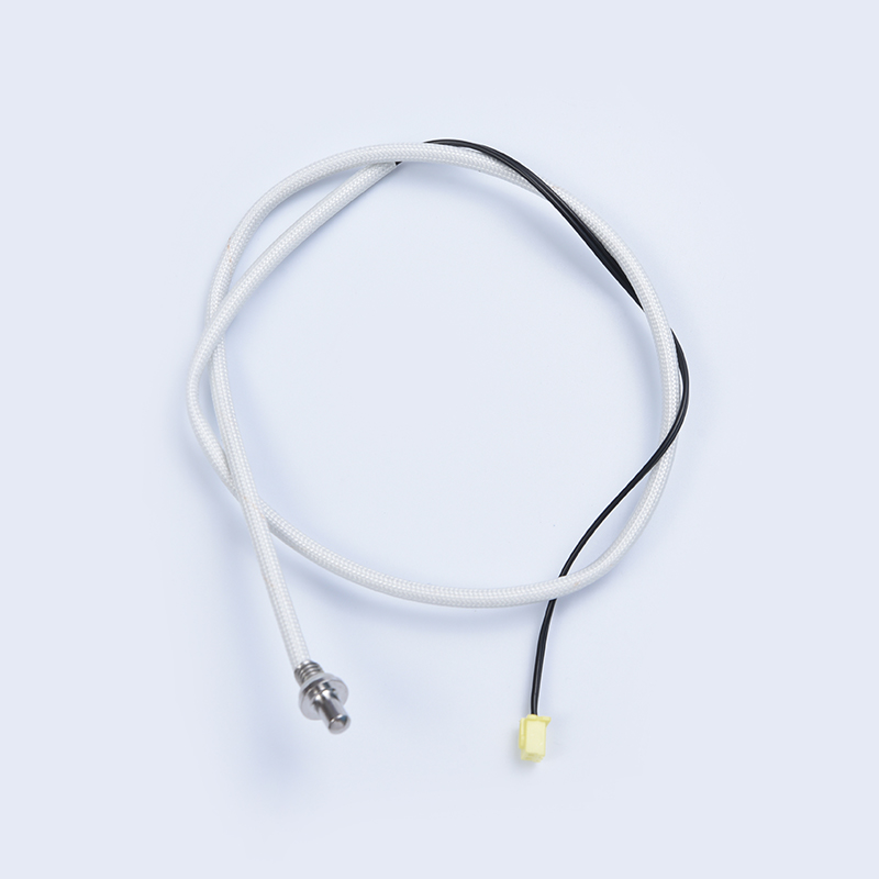 Coffee Machine NTC Temperature SensorUseful for coffee machine thermal regulation and overheating protection checks; it measures temperature near the heating element or water pathway as resistance falls.View Product →
A practical checklist for the next test
- Record the part number and nominal resistance at 25 °C.
- Confirm the sensor's actual temperature with a reference thermometer.
- Note meter lead resistance, and test at two temperatures.
- Inspect terminals, crimps, and wire before replacing the sensor.
- Compare the slope, not just one room-temperature number.
Resistance testing is not about finding one perfect number. It is about building a small, repeatable case: known temperature, known part, known meter setup, and a second reading that confirms the trend. Do that, and a good sensor will look good for the right reasons, while a bad one will show its weakness before it reaches the customer.