+86-0574-63316601


 中文简体
中文简体Content
When you set an air fryer and it switches off at just the right moment, or a rice cooker drops to keep-warm exactly when the grain has absorbed enough water, a small component is doing the thinking for the appliance. That component is the thermistor, a two-terminal resistor whose resistance changes with temperature. This article explains how a thermistor is used to measure temperature: the physical principle that makes it work, the circuit that reads its resistance, the mathematics that converts that reading into a temperature, and the practical details that decide whether the measurement stays accurate over years of use.
A Resistance That Changes with Temperature
Conclusion first: an NTC thermistor measures temperature because its resistance falls in a known, repeatable way as temperature rises. That single property is what turns a passive component into a sensor.
A thermistor is made from ceramic semiconductor materials, usually metal oxides, sintered into a small bead, chip or disc. There are two families. Negative temperature coefficient (NTC) thermistors decrease resistance as temperature increases; positive temperature coefficient (PTC) thermistors increase resistance and are more often used for overcurrent protection or self-regulating heaters. For temperature measurement, the NTC type dominates.
The change is large enough to be read without elaborate electronics. A typical 10 kΩ NTC thermistor rated at 25°C measures about 33.6 kΩ at 0°C and about 700 Ω at 100°C - a swing of nearly 50 to 1 across the range where most household appliances operate. An NTC temperature sensor therefore needs only a basic analog input on a microcontroller, while a thermocouple would require amplification and cold-junction compensation. This combination of large signal, low cost and small size is why thermistors appear in almost every temperature-controlled appliance.
How a Microcontroller Reads the Thermistor
Conclusion first: a microcontroller reads a thermistor through a voltage divider, because an analog-to-digital converter (ADC) measures voltage, not resistance.
The standard arrangement connects the thermistor and a fixed resistor in series across the supply rail, with the measurement node between them. The ADC measures the node voltage, and the resistance is calculated from that voltage. If the thermistor is on the low side and the fixed resistor on the high side:
Vout = Vcc × Rfixed / (Rfixed + Rthermistor)
When the thermistor warms and its resistance falls, more of the supply voltage drops across the fixed resistor, so Vout rises. When it cools, Vout falls.
A practical measurement chain has four parts:
- A stable supply voltage, typically 3.3 V or 5 V
- A fixed resistor with a tight tolerance, preferably 1% or better
- The NTC thermistor in a package suited to the operating environment
- An ADC with enough resolution to distinguish the smallest temperature step the design cares about
A typical 10 kΩ NTC thermistor with a B value of 3950, paired with a 10 kΩ fixed resistor and a 5 V supply, produces these readings:
| Temperature | NTC Resistance | Vout |
|---|---|---|
| 0°C | 33.6 kΩ | 1.15 V |
| 25°C | 10.0 kΩ | 2.50 V |
| 50°C | 3.6 kΩ | 3.68 V |
| 75°C | 1.5 kΩ | 4.35 V |
| 100°C | 0.70 kΩ | 4.67 V |
Notice the uneven spacing: between 0°C and 25°C the output changes by 1.35 V, while between 75°C and 100°C it changes by only 0.32 V. Sensitivity is naturally higher at lower temperatures. Designers either accept this, rearrange the divider to bias sensitivity toward the operating window, or correct it in firmware because the curve is smooth and repeatable.
Converting Resistance into a Temperature
Conclusion first: once the resistance is known, three standard methods convert it into a temperature: a lookup table, the B-parameter equation, or the Steinhart-Hart equation. The choice is a trade-off between simplicity, memory use and accuracy.
Lookup Table (R-T Table)
Manufacturers publish a resistance-versus-temperature table for each sensor type. The firmware stores that table, finds the two entries that bracket the current resistance and interpolates linearly between them. This is the fastest method on a small microcontroller and the most common in appliance control boards. The catch is that the table must match the sensor's B value. Pairing a B = 3435 table with a B = 3950 sensor produces errors of several degrees at both ends of the range.
B-Parameter Equation
For a moderate temperature span, the resistance follows:
R(T) = R25 × exp[B × (1/T - 1/298.15)]
where T is in kelvin, R25 is the resistance at 25°C and B is the material constant, typically between 3000 K and 5000 K for NTC thermistors. This equation needs only two constants and is simple to implement. It loses accuracy when the span exceeds roughly 50°C, but within a narrow window it is the fastest way to estimate temperature without a table.
Steinhart-Hart Equation
For the widest range and the best accuracy, the Steinhart-Hart equation is the standard choice:
1/T = A + B × ln(R) + C × (ln R)^3
The three coefficients, A, B and C (not to be confused with the material constant above), are fitted to the sensor's measured curve. With good coefficients, this equation holds to within a few hundredths of a degree across the rated span. A microcontroller evaluates it a few times per second, so the computational cost is negligible.
Whichever method is used, the sensor itself carries tolerance. A standard NTC thermistor has a resistance tolerance of about ±1% at 25°C and a B-value tolerance of ±1%, which together translate to roughly ±0.5°C to ±1°C of error at 100°C. If the design needs tighter accuracy, specify a higher-grade sensor or perform a one-point calibration on the production line.
Practical Considerations That Decide Real Accuracy
Conclusion first: the accuracy of a thermistor measurement is decided as much by installation and operating conditions as by the sensor element itself. In real appliances, four factors cause most of the error.
Self-heating. The bias current warms the sensor slightly above the measured medium, creating a persistent error. Keep power dissipation below roughly 1 mW for a glass-bead sensor. As a reference, a 10 kΩ sensor in a 10 kΩ divider with a 3.3 V supply dissipates about 0.27 mW at 25°C - safe, but easy to exceed if the supply voltage is raised or the fixed resistor is made much larger.
B-value matching. Two sensors with the same resistance at 25°C but different B values read the same at room temperature and diverge progressively away from it. Confirm that the B value of the production sensor matches the characterisation in the firmware; a mismatch is a common root cause of "good at 25°C, wrong at 90°C" behavior.
Packaging and response time. The bare ceramic element responds in a fraction of a second, but the encapsulation slows it down. Epoxy-coated beads react quickly and suit dry air moving across a heating element; metal or silicone-sealed probes are slower but survive water, steam and cleaning agents. Selecting a sealed probe for a wet application, or a fast epoxy bead for an air stream, matters as much as the electrical specification.
Placement. The thermistor measures its own local temperature. It must sit as close as possible to the point being controlled - the heating element, the cooking cavity or the liquid being heated. A few millimetres of separation, a draft from a cooling fan or a thick metal bracket that sinks heat can shift the reading by several degrees.
An appliance-grade thermistor system, specified and installed with these four factors in mind, holds its calibration for years. This level of predictability is what manufacturers rely on when they build a control algorithm around a low-cost component.
Thermistor Measurement in Real Household Appliances
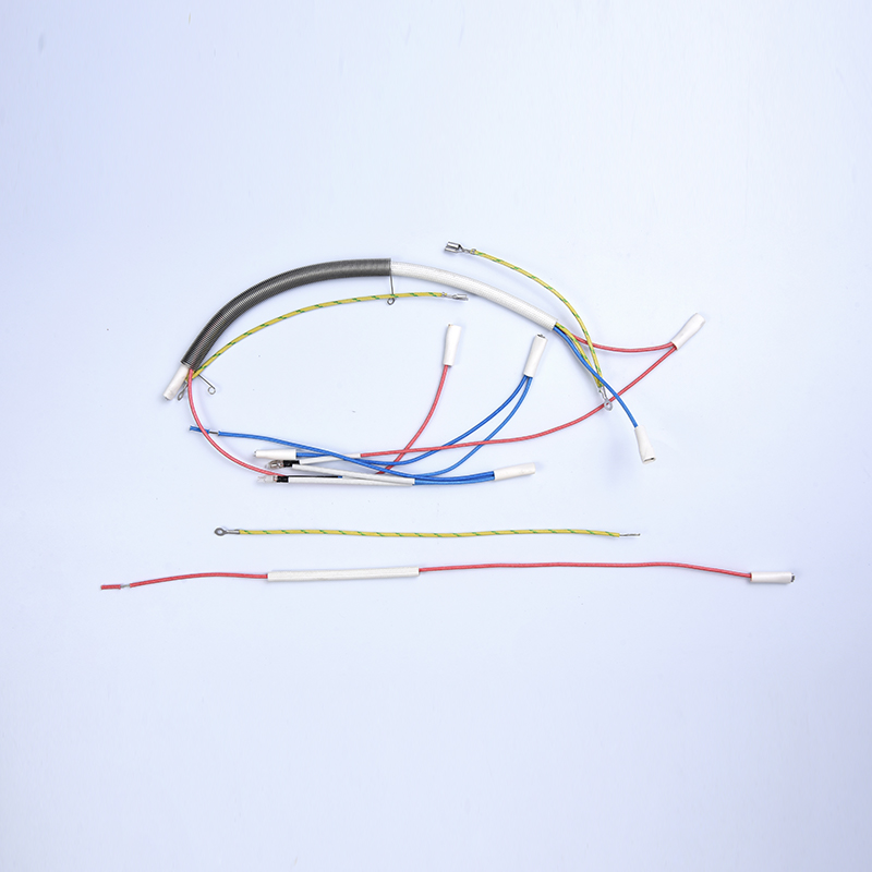
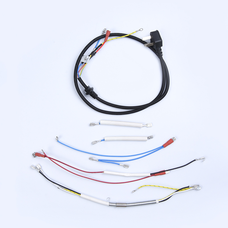
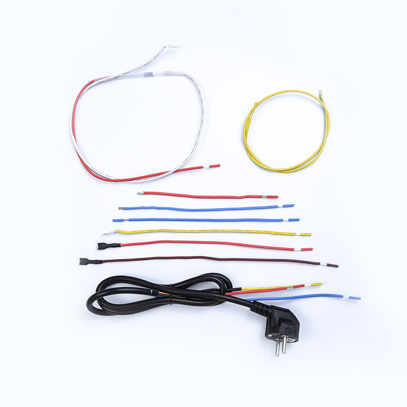
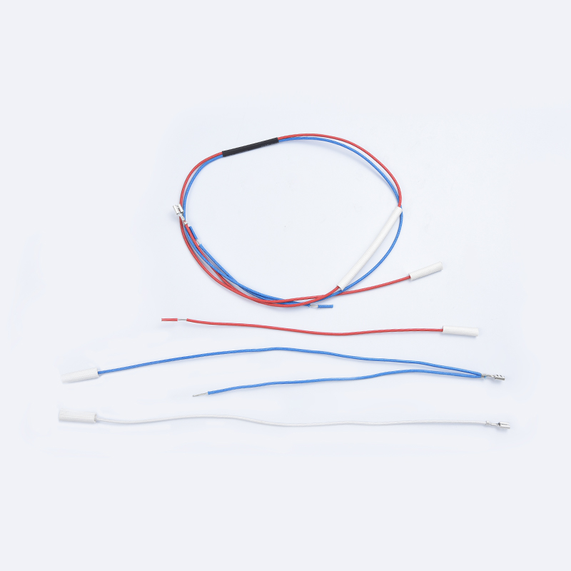
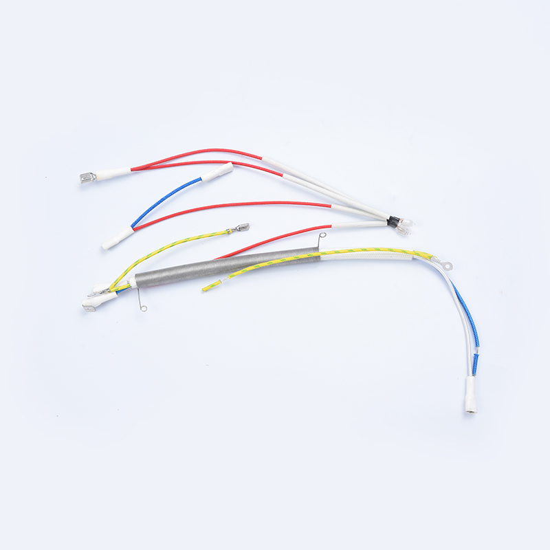
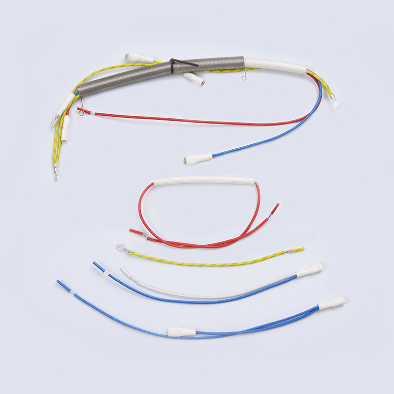
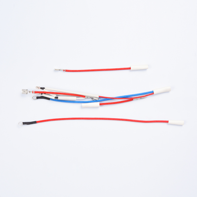
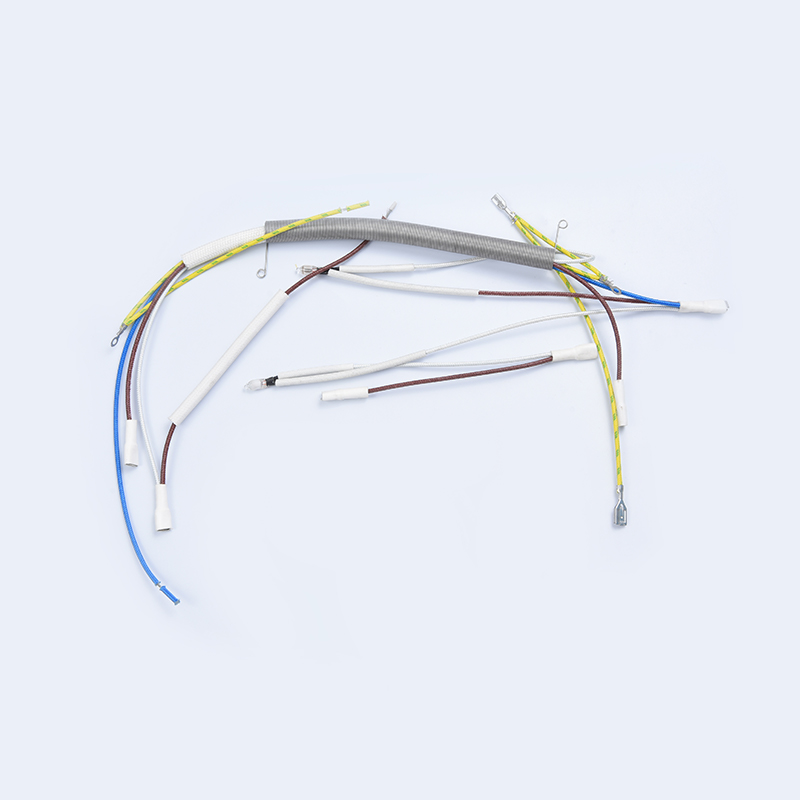
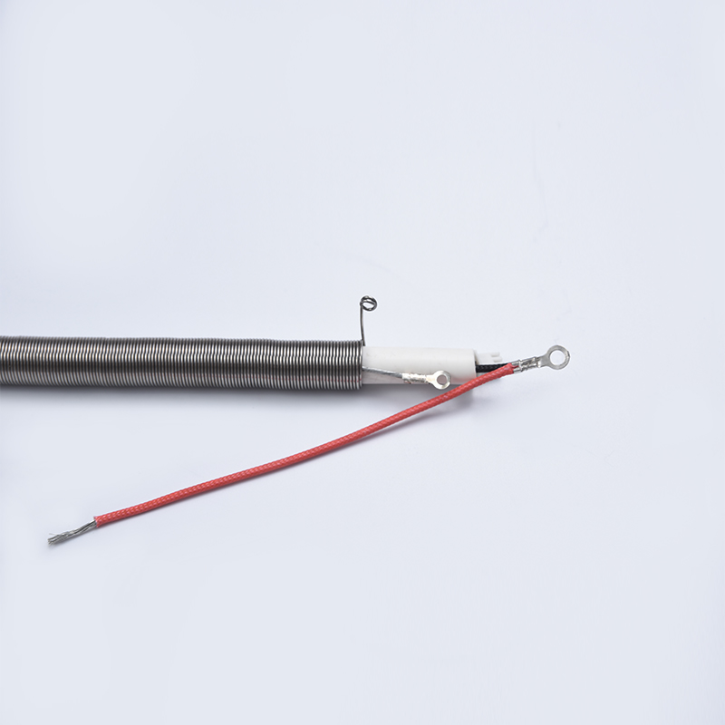
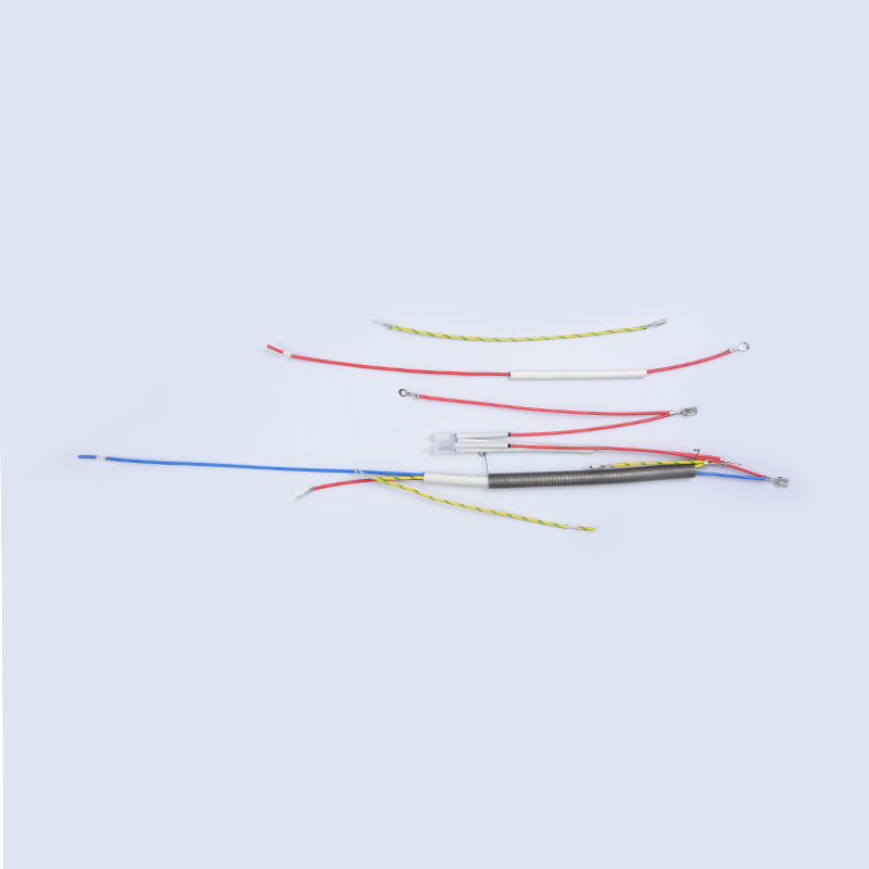
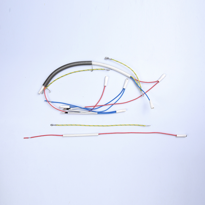
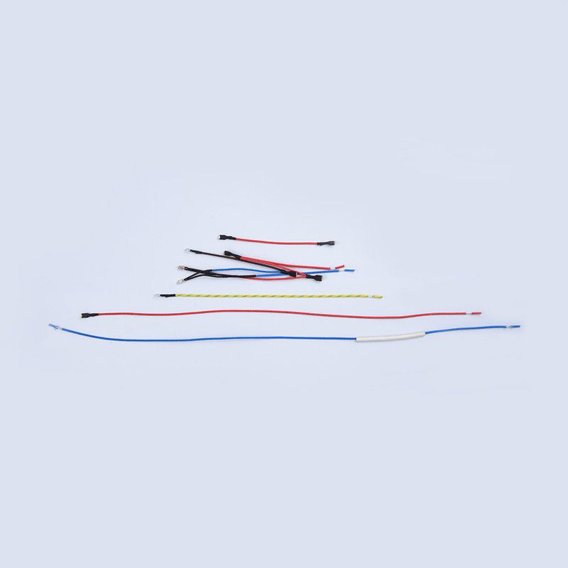
In production appliances, the thermistor never works in isolation. It connects to the control board through a wiring harness, and the connector, lead wires and insulation are part of the measurement system. A sensor with loose terminals or cracked insulation produces intermittent readings that no calibration can correct. Manufacturers therefore evaluate the sensor, the harness and the connector as one assembly rather than as separate commodity parts.
In an air fryer, the NTC sensor monitors the cooking cavity and reports to the controller, which switches the heater to hold the set temperature. The sensor must react quickly and stay stable across wide temperature swings; a slow sensor causes overshoot and uneven browning.
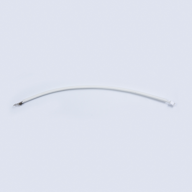 Air Fryer NTC Temperature Sensor from Cixi TengyuFast-response NTC sensors from a Chinese manufacturer support stable temperature control in air fryers, helping avoid overshoot and uneven browning during cooking cycles.View Product →
An electric kettle is a different test. The sensor mounts against the heating plate with a thermal seal, and the firmware monitors a rapid temperature rise. If the thermal coupling weakens, the kettle can keep heating past the boiling point before the controller reacts. A fast-response element combined with a reliable mounting structure is what makes an electric kettle shut off dependably every time.
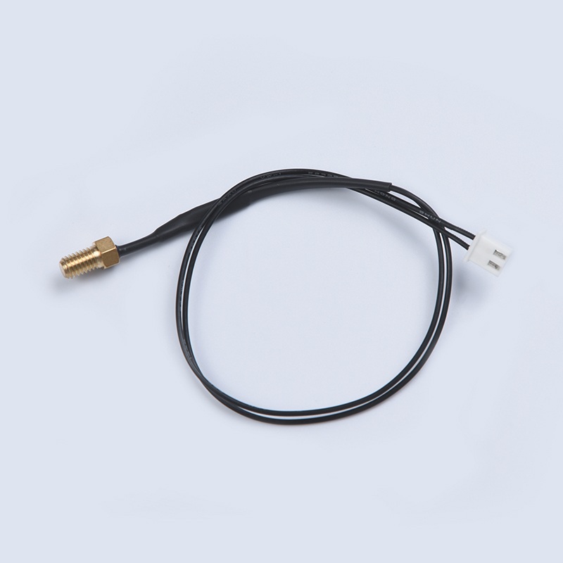 Electric Kettle NTC Temperature Sensor SupplierThis supplier offers NTC sensors for electric kettles, with thermal coupling and fast response to prevent overheating, ensuring dependable shut-off during boiling.View Product →
A rice cooker takes the same principle further. The sensor sits under the inner pot, and the controller watches the rate of temperature rise to decide when the water has been absorbed, then drops the power to keep-warm. It is a classic thermistor application: a low-cost sensor, a simple divider and a well-characterised curve working together to produce a consistent cooking result. The same approach appears in soymilk makers, food processors and electric pressure cookers.
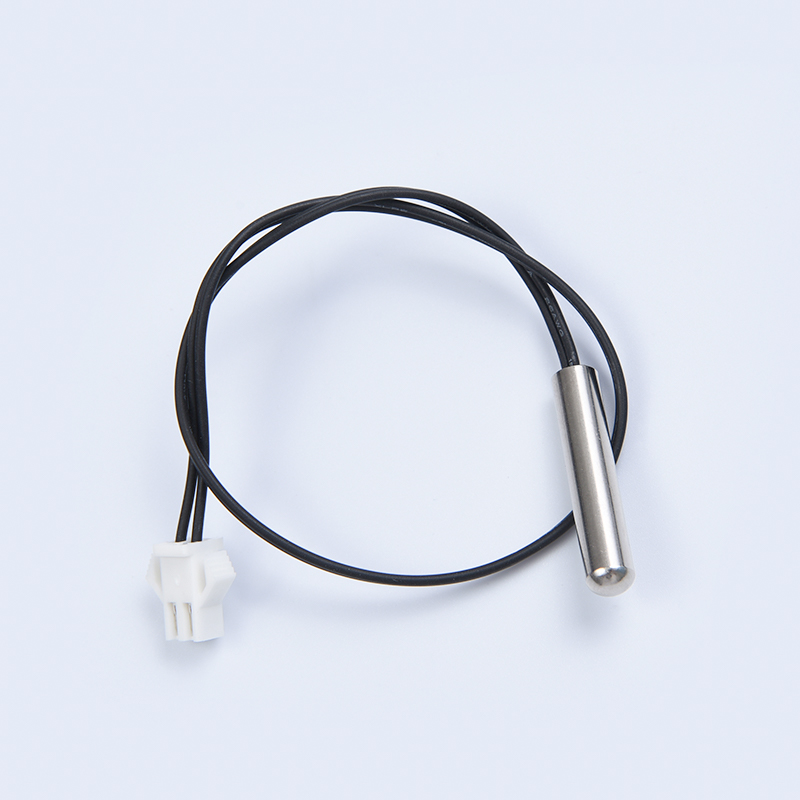 Rice Cooker NTC Temperature Sensor ManufacturerSensors from this maker are suited for rice cookers, monitoring temperature rise to manage water absorption and keep-warm function, supporting consistent cooking results.View Product →
From a procurement standpoint, the practical question is not whether thermistors measure temperature well - they do - but whether the supplied sensor is characterised with the correct R-T curve, packaged for the real environment and delivered with wiring that survives assembly and daily use. Choosing a wiring harness and NTC temperature sensor manufacturer that controls all of those elements together avoids the mismatch problems that show up after products reach the field.
The Bottom Line
A thermistor measures temperature because its resistance follows a repeatable, well-understood curve. The chain is short: a voltage divider converts resistance to voltage, an ADC digitises that voltage, and a lookup table or the Steinhart-Hart equation converts it to a temperature. Real accuracy comes from the details that the equations do not show - self-heating, B-value matching, packaging, placement and the wiring that connects the sensor to the controller. Handle those details properly, and a component that costs a few cents per unit holds an appliance within a degree or two of its target for years of daily operation.